

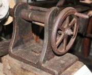
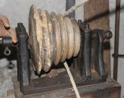
Lathes have been in use for over 2000 years (for turning bracelets, for example), but their evolution was remarkably slow.
Successful turning demanded a high level of skill and effort on the part of the turner, until the slide lathe started to find wider acceptance, c.1800. On the slide lathe, the tool is guided along the workpiece by slideways built into the lathe, rather than relying on hand-held tools. Movement is typically effected by leadscrews.
No great ingenuity was required to develop slide lathes, and few lathe developments would warrant the word 'invention'. Rather, their acceptance resulted from the maker's ability to construct a lathe with the required standard of accuracy, usability, and durability.
In fact the development of machine tools in general was remarkably slow, especially as they were needed to construct the new wonders of the age, particularly textile machinery, a field in which some of the most ingenious engineers were deeply engaged. Notable participants in both fields, who did advance the technology of machine tools, included Richard Roberts, Matthew Murray, and Fox of Derby.
The slow development evidently partly reflects limited demand rather than lack of capability. More sophisticated lathes would only be wanted by industrialists if they could do the work more cheaply or more accurately than by the traditional methods. A lathe could readily be made self-acting, but an operator still had to stand in attendance. Economics would demand that the operator could work several machines at the same time, or allow the work to be done by cheaper labour. However, there was surely an incentive on the part of the turners themselves to have a mechanised alternative to the sheer hard work involved in paring metal off a rotating workpiece with a hand-held tool. Another barrier was the difficulty in accurately making long, straight guiding surfaces, pending the arrival of another late developer - the planing machine. Another possible factor in the minds of potential purchasers is that although a self-acting slide lathe might be theoretically ideal for producing long, straight cylindrical surfaces, hand finishing would almost certainly be required to obtain a surface sufficiently smooth for, say, piston rods. Another factor in the wider acceptance of self-acting lathes was their ability to cut screws accurately, consistently, and relativeely cheaply.
It is noteworthy that by far the most sophisticated early lathes were not made for ordinary industrial production: they were used for producing scientific instruments (e.g. the screwcutting machines of Jesse Ramsden), clock and watchmaking, or for the amusement of rich clients (ornamental turning lathes).
Attempts to assign priority to any particular aspect of early lathe design are often futile. Surprisingly little is known about early slide lathes, dates of construction, or their makers, apart from some notable surviving examples, descriptions, or illustrations, including the products of Jacques de Vaucanson, Senot, Henry Maudslay, Joseph Clement and Richard Roberts. There is little doubt that Henry Maudslay should be given the credit for screwcutting slide lathes finding widespread acceptance in engineering production. This contribution has often been misinterpreted by lazy commentators to claim that Maudslay invented the slide lathe. Maudslay synthesised the key elements of precision lathe design and produced machines for industrial production.
We find vague mentions of early industrial slide lathes in sale notices. For example, in Manchester in 1805 we find 'One excellent clock maker’s cutting engine, one double fluting engine, one slide lathe new, .... two pair of excellent stock dyes and taps, several screw plates, six turners lathe spindles and headstocks, two lathe frames and wheels,....'[1]. Another Manchester sale in 1805 included 'Two Slide Lathes, 5 spacing[?] lathes, fluting engines; quantity iron rollers, smith’s tools, &c.'[2] In 1809 the sale of effects of Ridgway and Stott of Manchester in 1809 included 'sundry slide and other lathes for turning iron and copper bowls, rollers, &c.'[3].
At some point the more sophisticated examples became known as engine lathes. There is no exact definition of these machines, but they were usually of all-metal construction, and were self-acting - at least in the longitudinal direction - equipped for screwcutting, and power-driven. However the term 'engine lathe' was earlier applied to a class of machines used for producing decorative patterns, non-circular shapes, etc. These machines are now more commonly known as ornamental turning lathes, but the term 'engine turned' is still used for machine-cut patterns on watches, jewellery, etc. An early commercial producer was James Fox, who in 1767 was advertising a range of products which included '... all kinds of engine, oval and common lathes.... He also performs every branch of Turning, on Wood, Ivory, and the different Kinds of Metal, in Engine, Oval. or Common Lathes.'[4]. At the same time, 'engine lathes' were being used for industrial purposes, as shown by this 1786 advert: '.... exceeding neat Engine Lathe, Fluting Engine, and Several other Lathes, Machinery, &c. belonging the Cotton Manufactory…..'[5]
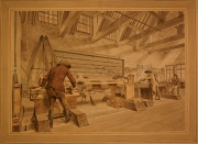
An early example of a heavy-duty industrial lathe having a tool guided in the 'X' and 'Y' planes was constructed by Jan Verbruggen at Woolwich Arsenal. The principal use of the water-powered machine was for boring cannon barrels, but it was also equipped for turning plain parts of the outer surface of the barrel. See illustration above, from Wikipedia, where higher resolution versions may be found[6]. It is entirely possible that Henry Maudslay saw this lathe during his time at Woolwich Arsenal.
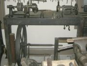
Early lathes are often found in museums. Only very rarely is the date of construction known, even approximately. It is unwise to attempt to assign a date based on the form of construction, as primitive features, such as wooden beds, continued to be adopted long after more sophisticated designs appeared.
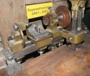
The Deutsches Museum in Munich does a fine job of presenting a range of machine tools from the 18th century up to the present day. Their earliest dated example is a watchmaking lathe made in Paris in 1741 by P.-F. Daneau (see photo). At first sight it appears highly sophisticated for its age, with the main elements being constructed of metal and made to a very high standard. Screws of five different pitches could be cut by engaging a key with one of five screwed portions of the spindle, which would advance the spindle axially as it rotated. However, it was still necessary to hold the cutting tool against the work by hand.
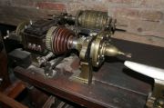
A much more complex lathe in the Deutsches Museum was made by J. Shega of Vienna, c.1767 (see photo). It is a Kunstdrechslerbank (ornamental turning lathe, engine turning lathe or rose engine). It was capable of cutting a variety of patterns and cutting screws, but again the cutting tool was hand-held.
It is probable that iron components for industrial lathes of the late 18th/early 19thC, namely headstocks with spindles, tailstocks, and tool rests were made for sale, leaving the purchaser to produce the wooden bed and drive arrangements. These parts were of relatively light construction, perhaps reflecting difficulties in transportation to remote places. One of the few known makers of component parts of lathes is revealed in a 1775 advert: 'SALISBURY. TO be SOLD, an extraordinary good Lathe, (with or without a collar and manderil, and treadlewheel) with a large wheel on frame, very convenient for shifting, and has three counter-wheels on it. Enquire of John Mendum, at Sir Alexander Powell's. N.B. The collar and manderil were made the best makers in England, Messrs. Baily and Macartney.'[7]
One form of construction which found favour within a fairly short window of time was the use a bar bed of triangular section. These first appeared in the mid 18th century, and came into wider use by the late 18thC. They probably fell out of favour in the second decade of the 19th century, although several makers in Germany favoured this style for much longer. Their wide acceptance was possibly influenced by the type being adopted and made available by the respected Henry Maudslay. Examples of Maudslay lathes can be seen in a number of museums. This c.1805 example in Australia, originally owned by Sir John Barton, is ascribed to Maudslay, Sons & Field. However, while the slide rest is fully consistent with Maudslay's design and construction, some other keys aspects, primarily the headstock and tailstock, are not Maudslay-like. The Henry Ford Museum in the USA has an example with a two-bar bed and a central leadscrew. Unusually, the carriage is held down by rollers pressing on the underside of the slideways. The lathe was gifted to the Ford Museum by Sir W. G. Armstrong, Whitworth and Co. Photographs here.
The triangular bed allowed the key components - headstock, tailstock and tool rest to be maintained in alignment, while the triangular form provided the easiest and most economical way of accurately manufacturing such a form of guidance by hand methods. Just the two upper faces needed to be made true, the quality of the underside being of little importance. Ease of hand production of the guiding surfaces was an important factor, given that the arrival of the planing machine was so surprisingly late. However, the triangular bar bed had limited stiffness due to its necessarily limited section size. A marked improvement came with the use of a pair of parallel bars, both guiding the same carriage. This appreciably increased the resistance twisting and transverse deflection, but demanded very high standards of manufacture. Henry Maudslay made twin bar lathes for industrial production
Henry Maudslay was by no means the first adopter of triangular bar beds, and neither was he the only prominent producer of industrial calibre examples. Matthew Murray used them on his large cylinder boring machines. They were also noted by Simon Goodrich as being used for the slideways of Matthew Murray's self-acting roller fluting engines when he visited Murray's works in January 1803. The earliest recorded example of a triangular bar bed lathe was made by Henry Hindley before 1758. He in turn influenced John Smeaton.
1796 Advert: 'TURNING LATHE. TO BE SOLD, (the Property of a Gentleman,) A VERY COMPLETE LATHE, on triangular Steel bar, with apparatus for Screws and Oval Engine. Enquire Miss. Leventhorpe's, in the Square.[8]
There is a good discussion of triangular bar bed lathes here.
Screwcutting Machines
A specialised form of lathe was used solely for cutting large screws. These were in use surprisingly early, as shown by the following advert from 1738. Unfortunately we know nothing about its construction.
'ALL Sorts of Iron Screws, from two Inches and a Half, to five Inches Diameter and upwards, the Threads whereof are cut by an Engine with great Exactness, are Made and Sold, at very reasonable Prices, by ROBERT BOWMAN, Anchor-Smith, at Whitehaven in Cumberland.'[9]
Highly sophisticated machines were in use by the mid 18th century for cutting small high precision screws for scientific instruments, clocks and watches. Fusee-cutting engines were particularly interesting, because they cut a thread on a hyperbolic profile.
In 1741 Henry Hindley showed John Smeaton his lathe for cutting accurate screws. He described it as a 'chock' (chuck?) lathe, and Hindley showed him 'the method employed to make the threads of the screw equiangular with the axis, that is, to free the screw from what workmen term drunkenness; and also shewed me how, by the single screw of his lathe, he could cut, by means of wheel work, screws of every necessary degree of fineness (and, by taking out a wheel, could cut a left-handed screw of the very same degree of fineness)...'.[10]
c.1795 Senot in France produced a precision machine which could cut relatively large screws, using change wheels to cut a range of pitches.
David Wilkinson in the USA obtained a patent in 1798 for a screwcutting machine, which he used to produce large iron screws. It could only cut screws with the same pitch as the leadscrew. A patent drawing of the machine exists, but it was produced about 40 years after the date of the patent. As drawn, the machine would have appreciable shortcomings in practical operation. An apparently novel feature was the use of a split nut to engage with the leadscrew. See David Wilkinson for more information about this machine, as illustrated in the post-patent drawing.
The Science Museum has on display two examples of screwcutting lathes by Henry Maudslay, dating from c.1800, one of these being a model. These lathes could cut a variety of pitches by using different leadscrews and/or change wheels. For more information, see Henry Maudslay: Machine Tools.
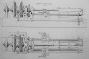
The Encylopaedia Metropolitana included a drawing and description of a large screwcutting lathe at Woolwich Dockyard. The drawing, reproduced here, is dated 1834, and, incidentally was drawn by P. Barlow Jr. (Peter William Barlow?). Screws of any pitch could be cut by changing the ratio of the gear wheels on the spindle and on the leadscrews. There were two leadscrews, enabling cuts to be taken on each side of the workpiece. To cut internal threads, the nut or other component to be threaded would be bolted to the slide rest and a threading tool mounted on a rotating boring bar. The machine was also described in the 'Cyclopedia of Useful Arts' published in 1854, where it is noted that the rear tool was intended to cut while the front tool was returning to the starting point on completion of its traverse, but this method 'does not produce very good results in practice'. It should be mentioned that Leonardo da Vinci's sketches included a screwcutting machine on the same principle, but clearly his sketches could have no influence on future technology.
The Encylopaedia Metropolitana also referred to a type of machine at Woolwich Arsenal for cutting original screws of any required pitch, and described it as 'One of the neatest and most perfect engines of this kind for short screws and taps .... constructed, and, we believe invented by the late Mr. Adam Reid.[11]. It appears that Reid's machine followed the principle of the fusee cutting machine (originally developed in France). The cutting tool was traversed by the action of an inclined plane moved by a rack and pinion, the pinion being fixed to the lathe spindle. Charles Holtzapffel notes that despite the length of the inclined plane (44"), the maximum size of screw that could be cut was limited to 1.6" diameter and 2.25" long.[12]
Towards Rational Designs
Towards the end of the 19th century, more or less standard forms of general purpose lathes were well established. They could be expected to be back-geared, to have compound slides, to be self-acting and capable of screwcutting, and have versatile arrangements for holding work. Lathes with these features, based on rigid iron box beds, were being produced for sale by a number of British makers from the second and third decades of the 19th century. Some examples are mentioned below.
Later, British lathes for jobbing shops often had gap beds to allow large diameters to be turned, and the carriages were often designed to hold work for boring.
A lathe which appears ahead of its time is the 1817 machine produced by Richard Roberts of Manchester, displayed in the London Science Museum.
More advanced examples were made by Fox of Derby. Two examples survive in the UK, thought to have been made c.1820-1830. For a discussion of the design features, and examples of lathes in Europe, see Fox of Derby entry.
From the 1830s, Joseph Whitworth started building lathes of a rational design, widely imitated by numerous other makers well into the 20th century. His 1835 lathe had an ingenious arragement for providing self-acting traversing and cross slide feed[13]. The oldest known surviving Whitworth lathe is at the Long Shop Steam Museum, made in 1839.
Most British makers followed Whitworth in adopting beds with flat-topped, dovetailed slideways. These were relatively straightforward to make accurately and gave good support to the carriage. Some other prominent early makers preferred one V and one flat guide, Richard Roberts and James Fox being early adopters of this arrangement. This avoids the need for gib strips, and good guidance would be maintained in the event of a moderate amount of even wear occurring.
American lathes of the early 19th century favoured a number of key features which logic would suggest had no great prospects, although in fact they remained popular for a very long period. Their design is further discussed below. However, as the century progressed, the design of the average American small to medium class of lathe became much more user-focused, and more productive, while the average British maker failed to move with the times.
The typical American lathe of the first half of the 19th century followed a common pattern, with a number of features which do not appear conducive to rigidity. They often had wooden beds fitted with metal guide strips. These guide strips tended to be of narrow vee form, whose acute angle suggests high frictional forces (due to wedging action), a situation not helped by the carriage (saddle) design. The typical carriage had two main parts, the upper part being arranged to be rise and fall using a jacking screw, and held in check by a heavy weight suspended from the carriage. Viewed in plan, the two parts of the carriage tended to be T-shaped castings of rather slender width and depth. The presence of the large weight hanging below the carriage precluded having the two sides of the bed joined by cross members. Tailstocks were broad for stability, but the wide span between the support feet - often exacerbated by having four slender legs - appears to introduce flexibility. Some lathes also had a similar 'bridge'-type support for the headstock. Self-acting carriage feed on these lathes tended to be provided by a chain, driven from the lathe spindle by gearing. Worm and wheel gearing was provided to drive the chain, typically having two worms, one above and one below the wheel. The worm shafts were interconnected by a frame, which when raised or lowered would engage one or other worm, or neither, to drive the chain in either direction.
Joseph Wickham Roe[14] is strangely quiet on the matter of this type of American lathe. The sole relevant mention is in reference to machines from one maker, Samuel Flagg, whose lathes are described as 'light and crude, with a wooden bed, wrought-iron strips for ways, chain-operated carriage, and cast gears.....'.
The narrow guide strips eventually gave way to a much more rational kinematic design, having a larger, less acute Vee paired with a flat surface. However, some makers persisted with the rise-and-fall weighted carriage.
Early Design Features, and the Problem of Dating
As previously stated, there are many lathes in preservation whose makers and dates of construction are completely unknown. We can identify certain features on different lathes which have common design features, and hope that dating information will eventually be found which will at least allow a specific era to be assigned.
The photographs on this page include examples of some primitive lathes. These may well be very old, but on the other hand their simple construction may reflect a lack of facilities available to the maker, or lack of knowledge of the 'state of the art'. The lack of dating knowledge discourages attempts to present these in chronological order, as will become apparent.
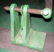
A particularly primitive example can be seen at Combe Mill (see photo). Its maker minimised the amount of metal, and the number of screwed fasteners. The adjustable wooden headstock and tailstock are fixed in place by wooden wedges. One minor detail which is common to many early lathes is the shape of the head on the tailstock centre's screw. The head is forged with 14 facets, a shape commonly produced by blacksmiths, perhaps over a very long period.
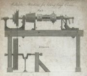
A drawing of lathe produced by 1809 by Charles Williams, brass valve maker of Southwark, shows a number of bolt heads of this 14-faceted shape (see illustration). This lathe also shows a cast iron headstock typical of many early lathes, having a conical main bearing, with a pointed centre supporting the outboard end of the spindle and taking the thrust force. The illustration here is dated 1814, but another version was included in a communication from Williams dated 5 January 1810 (hence the basis for sayiing that the lathe was in use by 1809)[15]
The same type of faceted screw head can be on the tailstock of the lathe at Cotehele Mill (see photo).
Despite the lack of dating evidence, it is clear from their characteristics that some of the surviving early lathes with iron headstocks and tailstocks date from the late 18th century. We can find examples of such lathes in contemporary adverts. For example, in 1791 textile machine maker Joseph Owen (Manchester) was advertising the sale of 'An Iron Lathe, with Iron Headstocks, a Foot Wheel, &c. Also a Wood Lathe, with very strong Iron Work, capable of turning a Pully, 16 Inches Diameter, with a large Wheel.'[16]
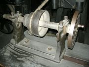
Mention has already been made of the typical headstock design, having a tapered main bearing at the 'chuck' end, and a pointed screw to support the outboard end of the spindle and to take the thrust. An alternative arrangement had a horizontally split main bearing. Beyond this there was little scope for varying the headstock design of early lathes.
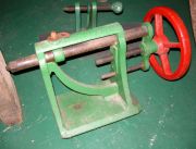
The tailstock, however, offered more scope for variety. Tailstocks were also known as 'loose headstocks', poppets, or puppets. On Maudslay's tailstocks, the barrel (spindle) was pushed towards the workpiece by a forcing screw, but the screw did not withdraw the barrel. Others had a screwed spindle, while many had an indirect-acting screw, as seen in the photo of the lathe. Examples can be seen on the lathes at Tiverton Museum (see photos). It is quite possible that some of these date from the late 18thC. However, the use of handwheels might well represent a later date, despite the otherwise archaic appearance of the tailstock. Of course, a screw with a handwheel might be a later replacement for the original. The two larger tailstocks at Tiverton show a typical arrangement for locking the barrel, using a sort of eyebolt through which the barrel passed.
A common feature on early lathes was the provision of a square tapered hole in the headstock and tailstock spindle to hold a centre, driving prong, or drill.
A lathe on display at Beamish Museum is said to have been used by George Stephenson in 1818. Its tailstock probably represents the next phase of development from the early type seen at Tiverton Museum. More difficult to make, assuming that the hole for the barrel was bored for a reasonable length. The headstock is unusual for the time, having split bearings at both front and rear, the front bearing presumably taking the thrust load.
The Museum of Bath at Work has a fine collection of old lathes, and the first of the Bath photos shows a step forward in development. The wooden bed is clad with iron, and although the headstock and tailstock design is still basically the same, the detailed design and quality are clearly improved from the earlier examples.
Published Histories of Lathe Development
A number of accounts of machine tool development have been published. Most display good standards of objectivity, but all reveal some nationalistic bias, which is partly understandable in view of the accessibility of material to the authors at the place and time they were writing.
A number of good books were published in English in the 1960s, written by Robert S. Woodbury, L T C Rolt, and W. Steeds. Prior to this the best known work had been written by Joseph W. Roe.
Woodbury provided an excellent review illustrating how many of the key features of 19th century industrial lathes were anticipated in special-purpose lathes during previous centuries.[17] He credits Henry Maudslay as a man of genius who synthesised the key elements when the time was right for the birth of the industrial cutting lathe. A less satisfactory aspect is the credit he gives to David Wilkinson in developing heavy general purpose industrial lathes, which he stated came into very wide industrial use, and 'would feel familiar to a modern machinist', yet he offers no illustration or detailed description. In contrast, while accepting that Maudslay built many precision lathes, he questions whether he had built a 'precision lathe of industrial size', writing 'But where is the evidence? Where are pictures, drawings, or descriptions of these machines?'
See Also
Sources of Information
- ↑ Manchester Mercury - Tuesday 26 March 1805
- ↑ Manchester Mercury, 6 August 1805
- ↑ Manchester Mercury, 31 January 1809
- ↑ Derby Mercury - 18 January 1787]
- ↑ Derby Mercury, 5 October 1786
- ↑ [1] Wikipedia for Jan Verbruggen
- ↑ Salisbury and Winchester Journal - 31 July 1775
- ↑ Hampshire Chronicle, 16 January 1796
- ↑ Newcastle Courant, 27 May 1738
- ↑ [2] The Miscellaneous Papers of John Smeaton, Civil Engineer, &c. F.R.S, by John Smeaton, 1814
- ↑ [3] Encylopaedia Metropolitana, Vol VIII, 1845
- ↑ [4] 'Turning and Mechanical Manipulation' Vol 2, by Charles Holtzapffel, 1856
- ↑ 'Tools for the Job' by L T C Rolt, HMSO, 1986
- ↑ 'English & American Tool Builders' by Joseph Wickham Roe, 1916.
- ↑ [5] Transactions of the Society for the Encouragement of Arts, .... Vol. XXVIII 1810, p.196ff
- ↑ Manchester Mercury - Tuesday 28 June 1791
- ↑ [6] 'History of the Lathe to 1850' by Robert S. Woodbury, Society for the History of Technology, Cleveland, Ohio, 1961


