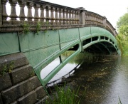
Culford Hall Bridge
in Suffolk
Also known as Culford Bridge, Culford School Bridge, and Cornwallis Bridge.
The bridge is in the grounds of Culford School, but there is permissive access for walkers (most conveniently from West Stow, where permissive footpaths are marked).
Built in 1803-4, it is a unique example of a cast iron bridge built to the patent of Samuel Wyatt. The rib castings feature stiff and efficient oval tubular sections.
The next oldest bridge having tubular cast iron ribs is Barrington's Bridge (1818) in County Limerick.
Culford Hall provides a rare example of a very early iron bridge which has survived without alteration.
British Listed Buildings description here
The following information is largely taken from an account of Samuel Wyatt's life and work by A. W. Skempton [1]:
In June 1800 Samuel Wyatt took out a patent for a new method of cast iron bridge construction, in which the arched ribs were assembled from cast iron voussoirs of unusual design. Voussoirs traditionally described the wedge-shaped stone blocks which formed the load-carrying arch. Here the voussoirs were iron castings forming segments of an arc. The top and bottom of the segment was of hollow oval section, joined by radial members. The arch ribs were connected transversely by iron plates. Arched plates between the ribs carried the infill up to roadway level. It is difficult to visualise the arrangement from the foregoing description, but the patent description and drawings are available online [2] [3] (Two links are given, both being required to see the two halves of a folded drawing!). Fig 9 is extracted from this source.
Wyatt proposed this form of construction for a bridge over the Thames in London. The eminent J. G. James wrote in the context of Wyatt's London Bridge proposal '..which, although no drawing survives, was presumably based on the system he patented (No. 2410, 10 June 1800) which had elegant but impractical cast voussoirs with hollow oval members. Possibly it was this which suggested to Wilson the idea of making the ends of his voussoir blocks hollow and inserting cast-iron dowels to provide continuity, instead of using wrought-iron straps.'[4]
J. G. James, writing in 1988, was unaware of the existence of a bridge made to Wyatt's patent, and it was not realised until 1996 that a bridge of this type exists at Culford Hall, built in 1804. It spans 60 ft and is 20 ft wide. The 80 tons of iron castings were produced by Hawks and Co of Gateshead. Seen from the roadway, it would not be obvious that it is an iron bridge, due to the adoption of masonry balustrades.
Since Culford Bridge only came to the attention of bridge historians in recent years, it is possible that any influence on the development of iron bridges has not received adequate recognition.
Details of Construction
Examination of the bridge reveals little about the secrets of its construction. No fasteners are evident, except for what might be small pins or rivets in a number of side panels. The lack of fasteners would be consistent with Wyatt's patent description of the ribs being connected with socketed joints, run with lead or cement where necessary. The arch ribs, of tubular cross section, have their ends socketed in transverse plates pierced by oval holes. These plates can be seen in Fig 3. Above the arch ribs are cast iron arched deck plates (see Fig 9). Fig 4 shows that the curvature of the deck plates is less than implied in Fig 9. Referring to the middle rib seen in Fig 4, there is evidence of weapage which suggests that the large elliptical foot is a separate casting from the rib casting, and provides a transition between the end of the rib and the pierced plate on the granite abutment.
The arrangement of the side panels is far from clear. Superficially we see flat panels with flared bottom edges, interrupted by radial ‘mouldings’. It appears that these ‘mouldings’ are actually transverse plates (see Fig 7, which shows the parting line of the plate casting, showing that the casting was made in a closed mould). In Fig 6 a number of small pins(?) can just be seen at the flared bottom of side panels. Clearly these have little strength and were perhaps used to maintain alignment during construction. It is not clear how the masonry balustrades are supported on the iron structure. Fig 8 (one of the side plates above the granite abutment) shows that at this location at least, the balustrade is not bearing on the side panel.
See Also
Sources of Information
- ↑ 'A Biographical Dictionary of Civil Engineers in Great Britain and Ireland, Vol 1', Thomas Telford Publishing, 2002
- ↑ [1] The Repertory of Arts and Manufactures, Volume 14, 1801
- ↑ [2] The Repertory of Arts and Manufactures, Volume 14, 1801
- ↑ 'Some Steps in the Evolution of Early Iron Arched Bridge Designs' by J. G. James, Newcomen Society, presented at the Science Museum, 11 May 1988


